


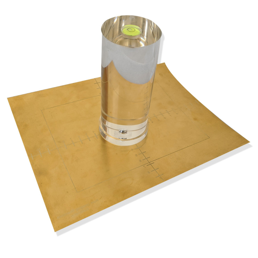
When the light field and radiation field do not agree, the image receptor may capture anatomy outside the intended exposure area. That makes field alignment a practical quality-assurance concern, not merely a setup detail.
A beam alignment device supports routine evaluation of field-to-beam coincidence. It helps compare the visible light field with the radiation field at the image receptor. Published methods have measured both field edges and calculated their deviation. Acceptance criteria remain dependent on facility protocol and applicable requirements. See the published field-congruence method.
The useful question is not simply whether a tool produces an image. The setup should let a qualified QA professional assess alignment under a repeatable, documented workflow. The sections below distinguish what the test measures from how a facility may perform it. They also outline practical considerations for choosing a QA phantom, including the beam alignment QA phantom.
What Does a Beam Alignment Device Test?
A beam alignment device evaluates whether the X-ray field is positioned and oriented as intended in relation to the imaging system. The central concept is light-field to radiation-field congruence: the area outlined by the collimator light should correspond closely with the area exposed when radiation is produced. This check helps identify whether the visible field represents the actual radiation field.
In practical terms, the test examines the edges of both fields. A measurement may locate the radiation and light-field edges, compare their centers, and calculate the resulting deviation. One diagnostic-radiology study describes a quality-assurance device that processed field-edge profiles and calculated deviation across all four edges. Read the published field-congruence method for its specific measurement approach.
The device may also support related geometry checks. These can include confirming that the X-ray beam is perpendicular to the image receptor, the detector or receptor receiving the exposure. Perpendicularity matters because beam angle and receptor alignment affect the relationship between the projected field and the recorded image. The exact setup depends on the imaging equipment, device design, and facility procedure.
Quick answer: A beam alignment device tests whether the light field and radiation field agree at the image receptor, while helping evaluate field edges, field-center alignment, and beam perpendicularity.
These are general quality-assurance concepts, not universal pass or fail values. Facility acceptance criteria, testing frequency, field size, exposure settings, and required tolerances should come from applicable requirements and equipment documentation. They should also follow the facility’s approved QA protocol. A published measurement result or research method should not replace qualified professional oversight.
Why Collimation and a Beam Alignment Device Matter in Radiology QA
Collimation and beam alignment connect the field selected at the control panel with the field that reaches the image receptor. When those fields do not correspond as expected, the displayed anatomy, exposed receptor area, and intended imaging geometry may no longer match. A beam alignment device can help QA personnel evaluate that relationship. The result may identify changes that warrant further investigation under the facility’s approved procedure.
Field-to-beam coincidence is therefore more than a mechanical check. It supports repeatable positioning and consistent image quality by helping confirm that the X-ray beam is perpendicular to the image receptor and that the collimated field is represented accurately. Better geometric control may also reduce avoidable retakes. That can help limit unnecessary patient exposure, although the effect depends on the cause of each repeat, the imaging protocol, and the broader quality-assurance program. A coincidence check does not by itself establish clinical image quality or prove that a system is safe for every use.
- It evaluates the relationship between the light field, radiation field, and image receptor.
- It can reveal changes in collimator positioning or beam geometry that merit qualified review.
- It provides a measurable QA record when the same facility-approved method is applied consistently.
Choosing between CR and screen-film methods
The readout method also affects workflow. A peer-reviewed comparison found no difference between computed radiography (CR) and conventional screen-film measurements of beam-collimator misalignment. However, the CR approach required more time, and its analysis required image-processing skills. That makes the choice a practical consideration for the facility, not simply a question of which method is newer. The appropriate detector, software, exposure approach, and review process should follow the equipment documentation and qualified QA oversight.
Published visual QA work has shown that light and radiation field congruence can be assessed with CR or an electronic portal imaging device. One studied method detected congruence within 1 mm under its reported conditions. That result belongs to the reported method and setting; it is not a universal tolerance for diagnostic radiography. A beam alignment device can support the test, but it does not replace acceptance testing, applicable requirements, professional interpretation, or a facility’s defined action limits and testing frequency.
How to Perform a Beam Alignment Test
A beam alignment test compares the intended light field or collimator setting with the radiation field recorded at the image receptor. The outline below describes the procedure’s logic, not a universal operating protocol. Exact distance, field size, exposure, tolerance, and testing frequency must come from equipment documentation and the facility QA program. Qualified QA personnel should oversee the test.
- Review the applicable procedure and prepare the room. Confirm which system, receptor, modality, and alignment question are being evaluated. Check the manufacturer’s instructions and local safety requirements before positioning any test device. Establish the measurement geometry specified for that system. Do not assume that a published research setup applies to your equipment.
- Position and level the test tool. Place the detector, marker tool, or phantom in the prescribed relationship to the image receptor. Use the light field to align the tool to the selected field and verify its orientation. One published visual QA example used a 100 cm source-to-surface distance and a 10 by 10 cm field at isocenter. But those values are study-specific examples, not default instructions for every installation (published visual QA method).
- Acquire the approved exposure. Set the field and exposure factors according to the facility’s documented protocol. Depending on the equipment and readout method, the test may use markers, a detector image, or sequential radiation and light-field exposures. A computed-radiography method, for example, exposed the detector to the radiation field before applying a slightly smaller light field (computed-radiography field method).
- Compare the visible or measured edges. Inspect markers or field edges on all relevant sides. Compare the radiation field with the light-field boundary, crosshair, or intended collimator position. Depending on the method, analysis may identify each edge and calculate the difference between field centers. Record the direction and magnitude of any observed deviation using the units and reporting format required by the local protocol.
- Document and evaluate the result. Record the system identification, setup used, exposure information, observed measurements, and reviewer details required by facility policy. Compare the result with the applicable tolerance. If the deviation exceeds the defined limit, or if the result is unclear or not reproducible, stop treating it as routine pass data. Escalate it under the facility’s QA and service protocol for review, follow-up testing, and corrective action.
For facilities evaluating a dedicated tool for routine collimator checks, the beam alignment QA phantom is one product-specific option. Its documented features should be considered alongside the facility’s equipment, field-of-view requirements, readout method, and qualified QA workflow.
Which Standards and Records Guide the Test?
A beam alignment test should sit within the facility’s established quality assurance program, not operate as a standalone checklist. The applicable requirements may include local regulations, the imaging system manufacturer’s documentation, the facility’s QA policy, and instructions from qualified personnel responsible for testing and interpreting results. These sources determine the test method, equipment setup, frequency, tolerance, and response to an out-of-range finding.
The FDA publication Routine Compliance Testing Procedures for Diagnostic X-Ray Systems provides a specific regulatory context. It describes procedures for routine testing of diagnostic X-ray systems as a means of screening for compliance with applicable Federal Performance Standards, including 21 CFR 1020.30-1020.32. The publication also distinguishes routine screening from more rigorous follow-up testing when needed. It should not be treated as a universal facility protocol or as a substitute for current state requirements, equipment instructions, or professional QA oversight.
Good records make the test useful over time. Depending on facility policy, documentation may identify the system and test device. It may describe the setup and method used, record the observed alignment result, and note the reviewer, date, and follow-up action. These are practical record categories, not a list of mandated fields. The responsible physicist or QA lead should confirm what must be retained and how results are evaluated.
When results change, the record should preserve enough context for a qualified reviewer to compare the finding with prior tests and determine whether additional investigation is appropriate.
How Do You Choose a Beam Alignment QA Phantom?
Choose a phantom by matching its measurement design to the test your facility actually performs. A device for routine diagnostic X-ray collimator testing is not interchangeable with a radiotherapy phantom designed to evaluate beam positioning away from isocenter. Start with the modality, then confirm the field of view, readout method, setup time, and records your QA program requires.
| Selection factor | Questions to ask | Why it matters |
|---|---|---|
| Test target and modality | Are you checking diagnostic X-ray collimation, beam perpendicularity, or radiotherapy beam positioning? | The phantom must represent the geometry and beam behavior being evaluated. |
| Field of view | Does the usable area match the equipment and field sizes in your protocol? | A suitable field supports consistent placement and clear interpretation. |
| Readout and workflow | Will results be read visually, from an image receptor, or through image-processing software? | CR-based methods can support alignment testing, but may require additional time and image-processing expertise. |
| Documentation and accessories | Does the package include instructions, positioning aids, and storage or transport equipment? | Clear documentation and repeatable setup help different staff follow the same local procedure. |
For diagnostic radiography, a product such as the RSD Beam Alignment QA Phantom is documented for routine collimator testing. It also supports checking that the X-ray beam is perpendicular to the image receptor. Its documented features include a brass plate, built-in spirit level, and custom field-of-view sizes upon request. Review the radiography QA phantom for field alignment and digital radiography QA tools if your application extends beyond this specific test.
Radiotherapy literature also describes an off-isocenter phantom evaluated with EPID imaging and repeated measurements for beam-positioning error. That example concerns treatment delivery geometry, not diagnostic X-ray collimator testing. In every case, select a tool that supports your facility protocol, equipment documentation, qualified oversight, and need for repeatable records.
When Should a Facility Request a Product-Fit Discussion?
A product-fit discussion is useful when an institutional buyer has defined the test objective but needs to confirm that a device suits the imaging system. Field of view, workflow, and documentation requirements should be considered together. Start with the intended test and modality, then consider how the result will be observed, recorded, and incorporated into the facility’s existing QA process. A qualified QA professional should also confirm the applicable procedure, equipment instructions, and local requirements.
Radiology Support Devices Inc., operating as RSD Phantoms, offers a Beam Alignment QA Phantom for routine collimator testing. The product is designed to help verify that an X-ray beam is perpendicular to the image receptor. Its documented features include a brass plate, built-in spirit level, and custom field-of-view sizes upon request.
This may be a suitable discussion point when a facility needs a focused beam-alignment device rather than a broader image-quality phantom, or when its required field of view and routine setup need clarification. Review the beam alignment QA phantom specifications, then request guidance if the intended test, modality, FOV, or workflow is not fully defined.
RSD Phantoms products are quote-based institutional purchases. A Request a Quote can help the facility discuss fit without assuming that one device covers every QA application.
Frequently Asked Questions
What does a beam alignment device evaluate?
It evaluates the relationship between the light field, radiation field, collimator, and image receptor. Depending on the device and workflow, the test can show whether the radiation field follows the intended collimated field and whether the beam is positioned as expected. It does not replace acceptance testing, qualified interpretation, or facility-specific QA requirements.
How is field-to-beam coincidence checked?
A typical workflow positions the test tool according to the equipment manual and facility protocol. The operator aligns it with the light field, exposes the detector, and compares the visible or analyzed radiation-field edges with the light-field markers. Published methods have used EPID, computed radiography, or film, but the detector, exposure sequence, distance, and field size should be selected by qualified staff for the system being tested.
Can computed radiography be used for collimator testing?
Yes. A published comparison used computed radiography for collimator and beam-alignment testing and found no difference from screen-film measurements for beam-collimator misalignment. The same study reported that computed-radiography testing took more time and that analysis required image-processing skills, so workflow and staff expertise should be part of the selection decision. Read the study.
What should I consider when selecting a QA phantom?
Start with the exact test objective, modality, field of view, readout method, setup requirements, documentation, and available accessories. For routine diagnostic radiography collimator testing, confirm that the tool fits the image receptor and supports the measurements your protocol requires. RSD’s Beam Alignment QA Phantom is described for routine collimator testing and includes a brass plate and built-in spirit level; custom field-of-view sizes are available upon request. Review the product details.
Contact us about your beam alignment QA needs
A product-fit discussion can help your team compare the test objective, field-of-view requirements, workflow, and documentation needs before selecting a QA phantom. Radiology Support Devices Inc. can review your application and discuss an appropriate beam alignment solution. To request a quote or discuss product fit, Request a Quote.